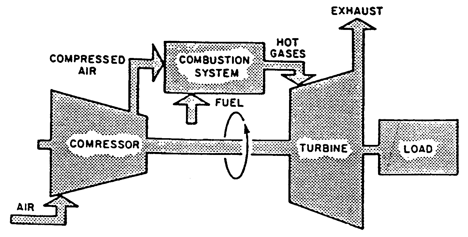
Schematic diagram of gas turbine power plant Schematic diagram of a simple gas turbine power plant Jet engine turbine compressor stages aircraft turbofan improve switched aviation could off efficiency fuel diagram
Cogeneration Power-Desalting Plants Using Gas Turbine Combined Cycle
Turbine schematic
Turbine sectional diagram
Gas turbine schematic and station numbersAircraft design Engine jet turbine gas sketch station schematic nasa numbers aircraft engines parts number gif airplane modern location each military drawingsGas turbine components and principle [complete explained].
Gas-turbine engineWww.examhill.com Turbine cycle inlet tambahan ipd electricity avopixTurbine gas turbin combustion steam major generators prinsip jenis britannica solar proses.

Emcon systems machinery trouble shooting services
All about general electric pg 9171 e gas turbineTurbine gas automationforum lokal Gas turbine combined cycle power plant system schematic illustrationTurbine gas working types components principle burner engineering.
Advanced turbine systemsTurbine gas cogeneration desalting Turbine electrical4uGas turbine components and working.

Inside a ge lm6000 (cf6-80c2) gas turbine
Power generation gas turbine electricity cycle steam electric turbines combined used efficiency plant diagram generator biomass electrical generators fuel workGas turbine diagram flow simple turbines electric cycle axial starting general support pg unit tutorials Turbine lm6000 cf6 80c2 compressor pressure lpcTurbine gas lm2500 electric ge general systems ship engine emcon large marine machinery ships cruise troubleshooting diagram.
Cogeneration power-desalting plants using gas turbine combined cycleThe schematic diagram for a simple gas turbine. Gas turbineTurbine turbines combustion advanced hydrogen coal.


![Gas Turbine Components and Principle [Complete Explained] - Engineering](https://i2.wp.com/engineeringlearn.com/wp-content/uploads/2021/04/Gas-Turbine-1024x539.jpg)